Control features | Control mode | Vector control 1 | Vector control 2 (Without encoder) | Vector control 2 (With encoder ) |
Startup torque | 0.5Hz 150% | 0.25Hz 180% | 0.00Hz 180% |
Speed adjustment range | 1:100 | 1:200 | 1:1000 |
Speed stabilization precision | ±5% | ±0.2% | ±0.02% |
Torque control | N | Y | Y |
Torque precision | N | ±5% | ±5% |
Torque response time | N | <20ms | <10ms |
Product
functions | Key functions | Undervoltage adjustment, switching of AC operation grounding, protective grounding and DC operation grounding, rotation speed tracing, torque limitation, multi-speed operation (up to 23 speeds), auto tuning, S curve acceleration/deceleration, slip compensation, PID adjustment, drooping control, current limiting control, torque control mode and speed control mode switching, manual/auto torque boost. current limiting, multi-functional input/output terminal |
Frequency setting mode | Operation panel setting, terminal UP/DN setting, host computer
communication setting, analog setting AI1/AI2/AI3, terminal pulse DI setting |
Frequency range | 0.00~300.00Hz Note: Upon the control mode of vector control 1 0.0~3000.0Hz, which can be customized according to the customer demand |
Startup frequency | 0.00~60.00Hz |
Acceleration/deceleration
time | 0.1~36000s |
Powered braking
capacity | Braking unit action voltage: 650~750V;
Operating time: 100.0s;
The braking unit can be embedded for V6−H−4T75G and below equipment |
DC braking capacity | DC braking initial frequency: 0.00~300.00Hz;
DC braking current: Constant torque: 0.0~120.0% Variable torque: 0. 0~90.0%
DC braking time: 0.0~30.0s;
there is no initial waiting time for the DC braking to realize quick braking |
Magnetic flux braking
function | Ongoing action and no action upon deceleration as option, no action upon deceleration at default |
Unique
functions |
|
|
|
|
Multifunctional M key | The unique multifunctional key is used to set the frequently used operations: JOG, emergency shutdown, running command reference mode switch , menu switching |
Multiple menu modes | Basic menu mode, fast menu mode. Menu mode of non-leave-factory value function codes, Menu mode of last changed 10 function codes |
Parameter copy | The standard operation panel can realize the parameter upload, download and display the copy progress. The user can select to forbid the overwriting of the uploaded parameters. |
Displayed/hidden
function code | The customer can select to display or hide the function codes by themselves. |
Dual 485 communication
ports | Dual 485 communication ports support Modbus protocol (RTU). The standard operation panel can realize remote control box function with a maximum distance of 500m. |
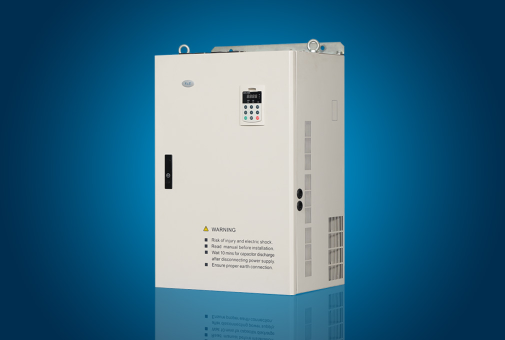
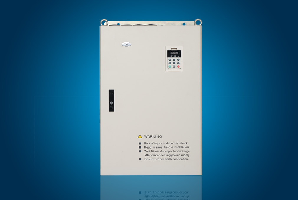
Operation panel | Button type or shuttle type operation panel optional, protection class: IP20 as standard, IP54 as option |
Common DC bus | The full series can realize common DC bus supply for several inverters. |
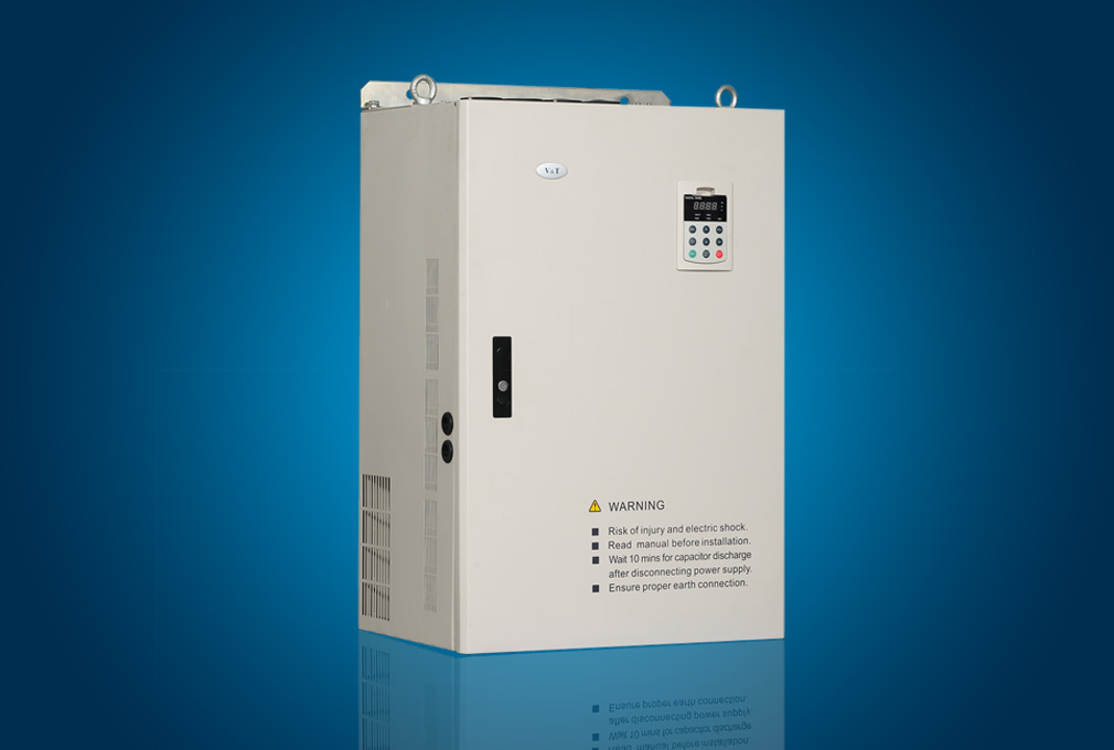
Independent duct | The full series adopts independent duct design and supports the installation of heatsink outside the cabinet |
Universal expansion
interface | Universal expansion board equipped with CPU for supporting customers secondary development: physical interface SPI bus, software protocol Modbus |
Expansion card | User’s secondary development card, injection molding machine interface card, PG feedback card, air compressor control card, communication adapter card, power monitoring card, phase sequence detection card, external power rectifying card |
Power-up auto-detection | Realizing the power-up auto-detection of internal and peripheral circuits, including motor grounding, abnormal +10V power supply output, abnormal analog input, and disconnection |
Protection
function | Power supply undervoltage, overcurrent protection, overvoltage protection, interference protection, abnormal comparison reference input, auto-tuning failure, module protection, heatsink overtemperature protection, inverter overload protection, motor overload protection, peripheral protection, abnormal current detection, output to ground short circuit, abnormal power failure during operation, abnormal input power, output phase failure, abnormal EEPROM, abnormal relay contact, temperature sampling disconnection, encoder disconnection, abnormal +10V power supply output, abnormal analog input, motor overtemperature (PTC), abnormal communication, abnormal version compatibility, abnormal copying, abnormal expansion card connection, terminal mutual exclusion detection failure, hardware overload protection |
Efficiency | At rated power, 7.5kW and below power class ≥93%, 45kW and below power class ≥95%, 55kW and above power class ≥98% |
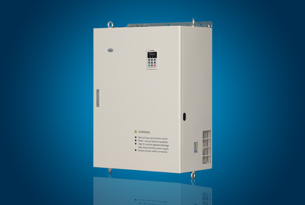
Environment | Operating site | The product shall be mounted vertically in the electric control cabinet with good ventilation. Horizontal or other installation modes are not allowed. The cooling media is the air. The product shall be installed in the environment free from direct sunlight, dust, corrosive gas, combustible gas, oil mist, steam and drip. |
Ambient temperature | -10~+40ºC, derated at 40~50ºC, the rated output current shall be decreased by 1% for every temperature rise of 1ºC |
Humidity | 5~95%, no condensing |
Altitude | 0~2000m, derated above 1000m, the rated output current shall be decreased by 1% for every rise of 100m |
Vibration | 3.5mm,2~9Hz;10 m/s2,9~200Hz;15 m/s2,200~500Hz |
Storage temperature | -40~+70℃ |